Tip
Check out:
our DEMO system
our Video tutorials
our GitHub sponsors => a way of supporting the project
Connection
Description
Here you can find information to the implementation and maintenance of connection-devices such as analog to digital converters.
Note
Only devices we tested are listed here.
If you have tested some on your own and want to contribute your know-how => send us the information to contact@growautomation.eu
Please include at least the information you see listed in the existing devices below.
Devices
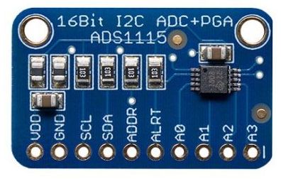
ADS1115
Links
Dependencies
apt
python3-smbus
i2c-tools
pip
adafruit-circuitpython-ads1x15
privileges
executing user must be a member of:
group gpio (usermod -a -G gpio USERNAME)
group i2c (usermod -a -G i2c USERNAME)
raspi-config
i2c must be enabled (raspi-config nonint do_i2c 0)
Config
Device model
Script: ads1115.py
Device
Connection:
If empty => the default i2c will be used
Else => ga_json[scl=GPIO_PIN,sda=GPIO_PIN]
Implementation
You will have to solder the pins to the pcb.
GA supports this converter natively.
Wiring
See also: raspberry pi i2c pinout
Power
VDD => 5V power supply
GND => ground
Connections to raspberry
SDA => GPIO #0, #2 or any free default gpio
SCL => GPIO #1, #3 or any free default gpio
Connections to analogue sensors
A0 to A3 => analogue out of the sensor
Issues
The contacts are sensitive to corrosion.
You would want to seal it by covering it with epoxy resin.
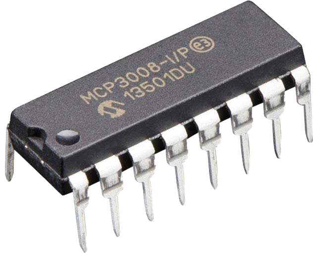
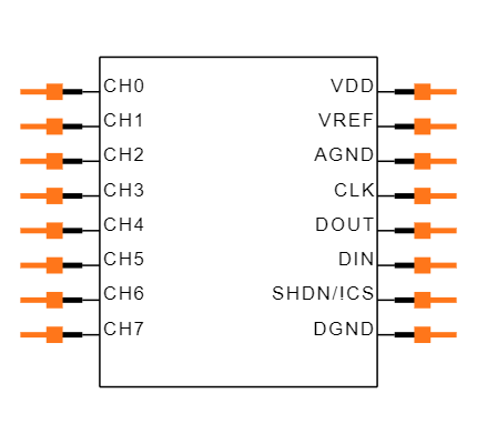
MCP3008
Tags
NATIVE
3.3V
8 INPUTS
4 GPIO
Links
Dependencies
apt
python3-smbus
pip
adafruit-circuitpython-mcp3xxx
privileges
executing user must be a member of:
group gpio (usermod -a -G gpio USERNAME)
group spi (usermod -a -G spi USERNAME)
raspi-config
spi must be enabled (raspi-config nonint do_spi 0)
Config
Device model
Script: mcp3008.py
Script argument: spi number
If empty => the default spi will be used
Device
Connection: GPIO_PIN
Implementation
GA supports this converter natively.
Wiring
See also: raspberry pi spi pinout
Power
VDD => 3.3V power supply
VREF => 3.3V power supply
AGND => ground
DGND => ground
Connections to raspberry
CLK => GPIO #11 or #21
CS => any free default gpio-pin
DIN => GPIO #9 or # 19
DOUT => GPIO #10 or #20
Connections to analogue sensors
CH0 to CH7 => analogue out of the sensor
Issues
Multiple spi-clients per bus were not successfully tested yet (spi would support it when using a cs-pin per client-device => see per example)